The following methods are used to measure the speed of rotation of an object: -
The choice of technique used for measurement is governed by the application range considered, degree of accuracy required, type of installation and original cost. In this section each type will be discussed and an overview of the importance of time measurement will also be discussed.
Mechanical Tachometer
This type of tachometer is a linkage of shafts, gears and rotating weights. When the input shaft which is seen horizontal rotates the vertical shaft it also rotates the weights attached to it which are hinged and free to move inward and outwards. The movement of these flyweights rotates a pointer which is calibrated to give the speed in desired units such as RPM.
Two main drawbacks of this are that the mechanical weights have inertia and hence not very accurate and secondly it does not give an indication of the direction of rotation.

Figure 5.8 Mechanical Tachometer
Electrical Tachometers
This type of tachometer could be as simple as a DC or AC generator that can determine the speed of shaft rotation by the amount of voltage the generator produces or the frequency of the output signal. The magnitude of the generator voltage and the frequency of the generated voltage will increase proportionally with speed. Frequency can also be measured by a photocell tachometer. The number of pulses produced by the photocell will increase as the speed of the shaft rotation increases.
The rotating field and the toothed rotor tachometers produce a waveform and the photocell uses a rotating disk that has a number of windows in it. A light source is positioned so that it will shine light through each window in the disk to a photocell detector as the disk spins. The disk is connected to the tachometer shaft, so when it turns the windows line up with the photocell and the photocell produces a pulse when it is struck by light. In each of these types of tachometers a pulse stream is produced and it is proportional to the speed of the tachometer shaft.

Figure 5.9 Digital Tachometer
Stroboscope
Also known as the “strobe”, is an instrument used to make a cyclically moving object appear to be slow moving, or stationary. The principle is used for the study of rotating, reciprocating, oscillating or vibrating objects. Machine parts and vibrating strings are common examples.
In electronic versions, the perforated disc is replaced by a lamp capable of emitting brief and rapid flashes of light. The frequency of the flash is adjusted so that it is an equal to, or a unit fraction below or above the object's cyclic speed, at which point the object is seen to be either stationary or moving backward or forward, depending on the flash frequency.

Figure 5.10 Stroboscope
In order to make a measurement, a mark is made on the object when it is stationary, and the object is spun up to speed. The oscillator is set to a low frequency to start with, and the LED is shone at the object where the mark is. At first, the mark will appear at random points around the object.
When it is stationary, the LED is flashing at the same frequency as the object is rotating. Since the frequency is known, the rotational speed is also known, and can be stated in RPM using the formula:
RPM = 60 × f
strobe
Magnetic Field Angular Position Sensors
These are similar shaft encoders, with one exception. They are capable of measuring the angle direction of a magnetic field from a magnet with <0.07° resolution. The advantages of measuring field direction versus field strength include: insensitivity to the temperature coefficient of the magnet, less sensitivity to shock and vibration, and the ability to withstand large variations in the gap between the sensor and magnet.
These sensors may be operated below 3 volts with a bandwidth response of 0-5 MHz. Output is a typical Wheatstone bridge permitting balanced output signals for noise immunity.
The main application of this sensor is to determine the angular position of a rotary axis. In this case, a permanent magnet is fixed on the engine axis just above the sensor. This magnet generates a directional magnetic field parallel to the surface of the sensor (Figure 5.11). This field works as a contactless interface between the orientation of the axis and the sensor.
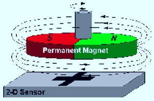
Figure 5.11 The permanent magnet speed sensor.
Wheel encoder
Figure 5.12 shows an example of a typical encoder wheel. The resolution of the encoder wheel is determine by the number of cycles or complete phases.

Figure 5.12 Wheel Encoder
The encoder is a sensor attached to a rotating object (such as a wheel or motor) to measure rotation. A typical encoder uses optical sensor(s), a moving mechanical component, and a special reflector to provide a series of electrical pulses. These pulses can be used as part of a feedback control system to determine translation distance, rotational velocity of a rotating component.
For instance, to measure the time it takes motor to rotate exactly 360 degrees or more or less, an encoder would be ideal. The sensor would be fixed on the shaft (the encoder wheel) would rotate with the shaft. The output of an encoder would be a square wave, so if you hook up this signal to a digital counter or microcontroller you can then count the pulses. Knowing the distance/angle between each pulse, and the time from start to finish, you can easily determine position or angle or velocity of the motor.
 Figure 5.13 Wind speeds for a wind turbine


