Power Semiconductor Devices

More on this category »

Latest Post

Showing posts with label Wind Energy Systems. Show all posts

The importance of speed in Turbine’s measurements

The power output of a wind turbine is proportional the cube of the speed. The speed is the most important parameter in evaluating the power from a turbine. It is often understated by manufacturers or misunderstood by buyers that the power rating of a wind turbine is only true at a given speed, know as the rated speed, which is neither too low nor too high, but somewhere where it is trusted that the wind turbine will be able to withstand the forces of rotation. These speeds are distinguished into four different regimes (Figure 5.13):
  1. Start-up Speed – This is the speed at which the rotor and blade assembly begins to rotate.
  2. Cut-in Speed –
    Cut-in speed is the minimum wind speed at which the wind turbine will generate usable power. This wind speed is typically between 7 and 10 mph for most turbines.
  3. Rated Speed –
    The rated speed is the minimum wind speed at which the wind turbine will generate its designated rated power. For example, a "10 kilowatt" wind turbine may not generate 10 kilowatts until wind speeds reach 25 mph. Rated speed for most machines is in the range of 25 to 35 mph. At wind speeds between cut-in and rated, the power output from a wind turbine increases as the wind increases. The output of most machines levels off above the rated speed. Most manufacturers provide graphs, called "power curves," showing how their wind turbine output varies with wind speed.
  4. Cut-out Speed –
    At very high wind speeds, typically between 45 and 80 mph, most wind turbines cease power generation and shut down. The wind speed at which shut down occurs is called the cut-out speed, or sometimes the furling speed. Having a cut-out speed is a safety feature which protects the wind turbine from damage. Shut down may occur in one of several ways. In some machines an automatic brake is activated by a wind speed sensor. Some machines twist or "pitch" the blades to spill the wind. Still others use "spoilers," drag flaps mounted on the blades or the hub which are automatically activated by high rotor rpm's, or mechanically activated by a spring loaded device which turns the machine sideways to the wind stream. Normal wind turbine operation usually resumes when the wind drops back to a safe level.
Wind speeds for a wind turbine Figure 5.13 Wind speeds for a wind turbine

Measurement of speed of rotation

The following methods are used to measure the speed of rotation of an object: -
  • Mechanical Tachometer
  • Digital Tachometer
  • Stroboscopes
  • Magnetic Field Angular Position Sensors
  • Wheel Encoder
The choice of technique used for measurement is governed by the application range considered, degree of accuracy required, type of installation and original cost. In this section each type will be discussed and an overview of the importance of time measurement will also be discussed.
Mechanical Tachometer
This type of tachometer is a linkage of shafts, gears and rotating weights. When the input shaft which is seen horizontal rotates the vertical shaft it also rotates the weights attached to it which are hinged and free to move inward and outwards. The movement of these flyweights rotates a pointer which is calibrated to give the speed in desired units such as RPM.
Two main drawbacks of this are that the mechanical weights have inertia and hence not very accurate and secondly it does not give an indication of the direction of rotation.
Mechanical Tachometer Figure 5.8 Mechanical Tachometer
Electrical Tachometers
This type of tachometer could be as simple as a DC or AC generator that can determine the speed of shaft rotation by the amount of voltage the generator produces or the frequency of the output signal. The magnitude of the generator voltage and the frequency of the generated voltage will increase proportionally with speed. Frequency can also be measured by a photocell tachometer. The number of pulses produced by the photocell will increase as the speed of the shaft rotation increases.
The rotating field and the toothed rotor tachometers produce a waveform and the photocell uses a rotating disk that has a number of windows in it. A light source is positioned so that it will shine light through each window in the disk to a photocell detector as the disk spins. The disk is connected to the tachometer shaft, so when it turns the windows line up with the photocell and the photocell produces a pulse when it is struck by light. In each of these types of tachometers a pulse stream is produced and it is proportional to the speed of the tachometer shaft.
Digital Tachometer Figure 5.9 Digital Tachometer
Stroboscope
Also known as the “strobe”, is an instrument used to make a cyclically moving object appear to be slow moving, or stationary. The principle is used for the study of rotating, reciprocating, oscillating or vibrating objects. Machine parts and vibrating strings are common examples.
In electronic versions, the perforated disc is replaced by a lamp capable of emitting brief and rapid flashes of light. The frequency of the flash is adjusted so that it is an equal to, or a unit fraction below or above the object's cyclic speed, at which point the object is seen to be either stationary or moving backward or forward, depending on the flash frequency.
Stroboscope Figure 5.10 Stroboscope
In order to make a measurement, a mark is made on the object when it is stationary, and the object is spun up to speed. The oscillator is set to a low frequency to start with, and the LED is shone at the object where the mark is. At first, the mark will appear at random points around the object.
When it is stationary, the LED is flashing at the same frequency as the object is rotating. Since the frequency is known, the rotational speed is also known, and can be stated in RPM using the formula:
RPM = 60 × fstrobe
Magnetic Field Angular Position Sensors
These are similar shaft encoders, with one exception. They are capable of measuring the angle direction of a magnetic field from a magnet with <0.07° resolution. The advantages of measuring field direction versus field strength include: insensitivity to the temperature coefficient of the magnet, less sensitivity to shock and vibration, and the ability to withstand large variations in the gap between the sensor and magnet.
These sensors may be operated below 3 volts with a bandwidth response of 0-5 MHz. Output is a typical Wheatstone bridge permitting balanced output signals for noise immunity.
The main application of this sensor is to determine the angular position of a rotary axis. In this case, a permanent magnet is fixed on the engine axis just above the sensor. This magnet generates a directional magnetic field parallel to the surface of the sensor (Figure 5.11). This field works as a contactless interface between the orientation of the axis and the sensor.
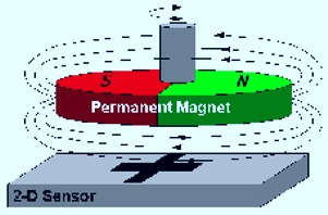
The permanent magnet speed sensor Figure 5.11 The permanent magnet speed sensor.
Wheel encoder
Figure 5.12 shows an example of a typical encoder wheel. The resolution of the encoder wheel is determine by the number of cycles or complete phases.
55 Figure 5.12 Wheel Encoder
The encoder is a sensor attached to a rotating object (such as a wheel or motor) to measure rotation. A typical encoder uses optical sensor(s), a moving mechanical component, and a special reflector to provide a series of electrical pulses. These pulses can be used as part of a feedback control system to determine translation distance, rotational velocity of a rotating component.
For instance, to measure the time it takes motor to rotate exactly 360 degrees or more or less, an encoder would be ideal. The sensor would be fixed on the shaft (the encoder wheel) would rotate with the shaft. The output of an encoder would be a square wave, so if you hook up this signal to a digital counter or microcontroller you can then count the pulses. Knowing the distance/angle between each pulse, and the time from start to finish, you can easily determine position or angle or velocity of the motor.

Electrical Measurements

Energy related measurements concerned with electricity production and consumption are usually derived from three elements namely: the electrical current, voltage and resistance of the load. These three variables are directly linked with the energy or power consumption of the load and hence it is common to see a single meter combining these to give a direct reading of the energy consumption.
Multimeters are very useful test instruments. By operating a multi-position switch on the meter they can be quickly and easily set to be a voltmeter, an ammeter or an ohmmeter. Two devices can be used to measure the electrical measurements: analog and digital multimeters as shown below in Figure. 5.3.
Digital and Analog Multimeters Figure 5.3 Digital and Analog Multimeters
As far as power is concerned, the most common unit of power consumption measurement on the electricity meter is the kilowatt hour, which is equal to the amount of energy used by a load of one kilowatt over a period of one hour, or 3,600,000 joules. Some electricity companies use the SI mega joule instead. Modern electricity meters operate by continuously measuring the instantaneous voltage (volts) and current (amperes) and finding the product of these to give instantaneous electrical power (watts) which is then integrated against time to give energy used (joules, kilowatt-hours etc). The meters fall into two basic categories, electromechanical and electronic, as shown in Figure. 5.4.
The mechanical electricity meter has every other dial rotating counter-clockwise. The most common type of electricity meter is the Thomson or electromechanical induction watt-hour meter, invented by Elihu Thomson in 1888. it work by counting the revolutions of an aluminium disc which is made to rotate at a speed proportional to the power. The metallic disc is acted upon by two coils. One coil is connected in such a way that it produces a magnetic flux in proportion to the voltage and the other produces a magnetic flux in proportion to the current.
A modern digital electronic wattmeter/energy meter samples the voltage and current thousands of times a second. The average of the instantaneous voltage multiplied by the current is the true power. The true power divided by the apparent volt-amperes (VA) is the power factor. A computer circuit uses the sampled values to calculate RMS voltage, RMS current, VA, power (watts), power factor, and kilowatthours. The simple models display that information on LCD. More sophisticated models retain the information over an extended period of time, and can transmit it to field equipment or a central location.
Measurement of Power Figure 5.4 Measurement of Power
Wind speed is the most important factor directly proportional to the power output of a wind turbine.
Various types of anemometer are used to measure the velocity, usually of air.
The ‘cup type’ air speed measurement
(Figure 5.5) is used for free air and has hemispherical cups on arms attached to a rotating shaft. The shape of the cups gives a greater drag on one side than the other and results in a speed of rotation approximately proportional to the air speed. Velocity is found by measuring revolutions over a fixed time.
Cup Type Anemometer Figure 5.5 Cup Type Anemometer
The ‘vane anemometer’
(Figure 5.6) has an axial impeller attached to a handle with extensions and an electrical pick-up which measures the revolutions. A meter with several ranges indicates the velocity.
Vane Anemometer Figure 5.6 Vane Anemometer
The ‘hot-wire’ anemometer’
(Figure 5.7) is a probe terminating in an extremely small heated wire element when subjected to a fluid stream it cools to an extent, which depends on the velocity of the fluid passing. The resulting change in resistance of the element is measured by a bridge circuit and is related to velocity by calibration.
50 Figure 5.7 Hot-Wire Anemometer